1966年ごろアメリカへ輸出され、40年ぶりに帰国を果たしたトリオ製の受信機です。
LAFAYETTE(ラフィエットとアメリカ人は発音)というブランドです。ほかにも JR-60、
9R-59、9R-42 などが LAFAYETTE ブランドで輸出されました。
本機は JR-60と同じかと思ったら、大違いでした。3.5MHz帯~50MHz帯のハムバンド専用
で、第一局発可変で第一IFが 2.608MHz のダブルスーパーでした。9R-59D と同じく、
安物のメカフィルが使ってあります。(Qマルチの方が操作は楽しいのですが。)BFO
は LC発振です。プロダクト検波回路と100KHz のマーカーが付いています。ゼネカバ
ではないので3連バリコンが鎮座していなく、さびしいです。
まずカバーをはずして洗剤を付けて水洗いしました。シャーシ上にはほこりが積もって
いましたが、水洗いするほどでもなく、雑巾で拭いたらきれいになりました。ガラスに
印刷した白い周波数目盛がしっかりしていたので油断して、洗剤を付けてブラシで軽く
こすったら、少しはがれてしまいました。
十分乾かして、シャーシ内部を目視でチェックした限りでは、問題はなさそうでした。
ケミコンは本ページに記載のある「ESR テスター」でチェックし、若干の劣化は感じら
れましたが、使えないほどではないのでそのままとしました。真空管は TV-7D/U でテ
ストしたら、いずれも高gmでした。
スライダックにつないで恐る恐る電圧を上げていったら、一応動作しているようでした
が、感度が悪いです。回路図と調整方法がBAMAにあったのでダウンロードして調整
を始めました。メカフィルのマッチングトランスの周波数がずれていて、調整したら感
度がだいぶ良くなりましたが、まだ△です。
3.5MHz 帯の局発コイルの調整が妙にクリティカルで感度も悪く、復調音も変なので、
それにつながっている 750Ωをチェックしたところ、2kΩほどになっていて、押さえる
と抵抗値が変わったり、発振が止まるようでした。ほかの抵抗(1/4Wのソリッド抵抗が
ほどんど)をチェックしたら、案の定、抵抗値が+20% から2倍になっていました。(
だから昔からソリッド抵抗は大嫌いです。)実害ありそうなところのだけをカーボン抵
抗に交換しました。
IFの周波数の信号を入れて IFT とメカフィルの周波数を調整し、局発のコイルとトリ
マーで周波数目盛と受信周波数を合わせ、ANT と RF のコイルのコアを調整し、それなり
の感度になりました。しかし、28MHz帯と 50MHz帯はノイズが少ないので、感度が低いよう
に思えます。ダブルスーパーなのに。
レストアのついでに、AC 117V 仕様から AC 100V 仕様に変更しました。電源トランスに
は 100V のタップがあるので問題ありませんが、局発の 6AQ8 は専用のヒータートランス
で常時点灯式です。(ヒータースイッチを付ければいいのに。)ジャンク箱をひっかきま
わしたら、100V/115V 用のヒータートランスが出てきました。それを使って配線しかけ
て気付きました。ヒータートランスは 117V用のままでもできるんです! 常時点灯をしな
ければ。電源トランスの 100V 端子に 100V を加え、117V 端子にヒータートランスの一
次側をつなげばよいのでした。(オートトランス式です。だったら電源トランスの 6.3V
端子につなげばいいだろうと言われそうですが、そうすると配線の変更が多くなるので、
と苦しい言い訳。)
途中で思いましたが、近代的なSSGがあっても、ディップメータは便利です。ダイヤル
をグルっと回せば瞬時に数MHzの可変ができ、かなりズレた受信周波数が判り、吸収型波長
計にすれば局発が発振していることを確かめられますから。やっぱり「テスターの次はディ
ップメータ」ですね。
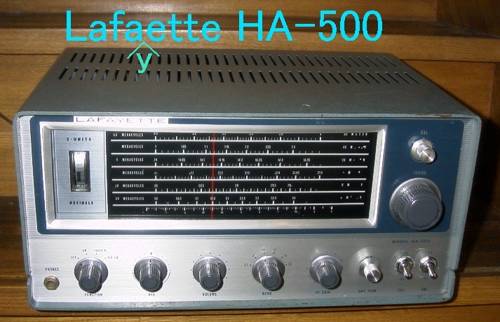
This is one of the Kenwood ("TRIO" at that time) made shortwave (ham band only)
receivers sold in the US under "Lafayette" brand. The model is an "HA-500" double
conversion superhet receiver exported to the US in 1966 or so and finally returned
to Japan 40 years later.
The fist local oscillator frequency is variable and the first IF is 2.608MHz. The
second IF is 455KHz. Two inexpensive (simple) 455KHz mechanical filters are used.
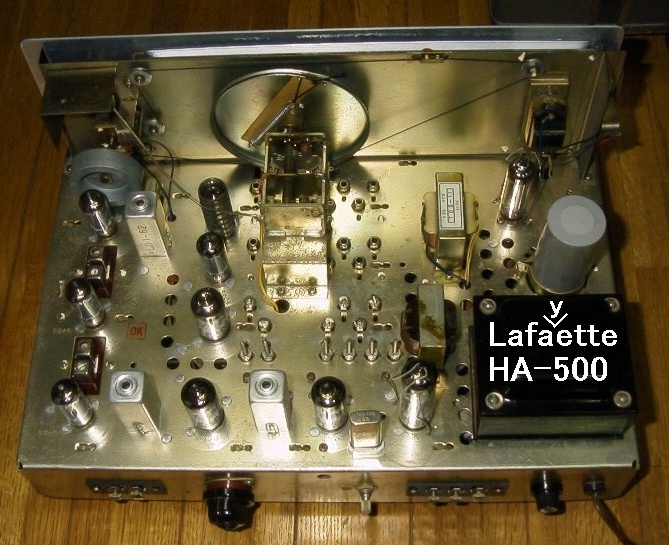
First, I cleaned (washed) the cabinet and wiped the chassis with a damp cloth.
Visually checked the components and tested the tubes with the TV-7D/U. All the
tubes tested very good. Then, I checked electrolytic capacitors with the ESR tester
I made. They were all OK.
After adjusting the IF coils, I tried to adjust the local oscillator frequency. I
noticed the local oscillator is unstable and sometimes it stopped oscillating. I
found a 750 ohm resistor is bad. Checking all the solid resistors revealed that
most of them have 20 to 100% higher values than color coded. (I hate them.) So, I
replaced those that affect the performance with carbon film resistors.
Then I adjusted the two IF circuits (coils) using a modern signal generator. Then,
adjusted the local oscillator frequencies and antenna and RF coils. Now the
sensitivity is good. But on the 28MHz and 50MHz bands, the sensitivity may not be
as good because the noise is not as loud as other low bands.
In addition, I modified the AC power wiring to the power from 117V to 100V for use
in Japan. A separate heater transformer was used to power the local oscillator
tube's heater as long as the AC 117V is fed. This heater transformer did not have
a 100V tap. So, I connected the heater transromer's primary widing to the 117V tap
of the (main) power transfomer.
While adjusting the local oscillator frequencies, a gate dip meter was very useful
even now because, unlike the modern signal generators, you can vary the oscillating
frequency very quickly by just turning the dial to find out the actual receiving
frequency way off from the frequency on the dial. Also, with at dip meter, you can
check that the local oscillator is really oscillating.