|
Record of Updates:
8-2-2025 Added UY-627B and HT-5001.
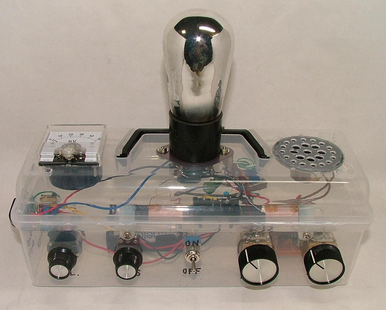
7-23-2025 Added a regenerative radio built in a clear plastic case
5-26-2025 Added some Japanese original tubes (UY-807B, KY-84A, Special 30) and UG-6P7G.
4-24-2024 Added photos of some Western Electric and other tubes.
4-16-2024 Added a power-transformer-less "Ultradyne Receiver" and a 6-transistor superhet for parts testing.
WARNING: In case you build equipment/gadget listed here, I would be happy to help you do so by giving you
advices by e-mails as long as my time and knowledge allow. However, I cannot guarantee that the
equipment/gadget will work to your satisfaction. Also, there are lethal high voltages (as high
as 800V) involved in some of the equipment. Please build any of those very carefully AT YOUR
OWN RISK. Please send your comments or questions, if any, to the following.
![]()
【1】Photographs of the Equipment/Gadgets I Built(Clic on the thumbnail for details)
●Regenerative Radio that works at about 2.5V filament and at 3.6V B voltages!
●Two IC Little Radio
●Six Transistor Superhet Radio for parts testing
●Power transformer-less Ultradyne Receiver
●Power Transformer-less Regenerative Radio with an RF amplifier stage
●Power Transformer-less Regenerative Radio with a feedback adjusting circuit
● Power Transformer-less Regenerative Radio with a tuning indicator (meter)
●Regenerative radio = Copy of a kit once sold by "Kagaku Kyouzai-sha".
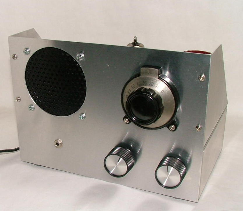
●Power Transformer-less Regenerative Radio(2nd Model)
●Power Transformer-less Regenerative Radio(1st Model)
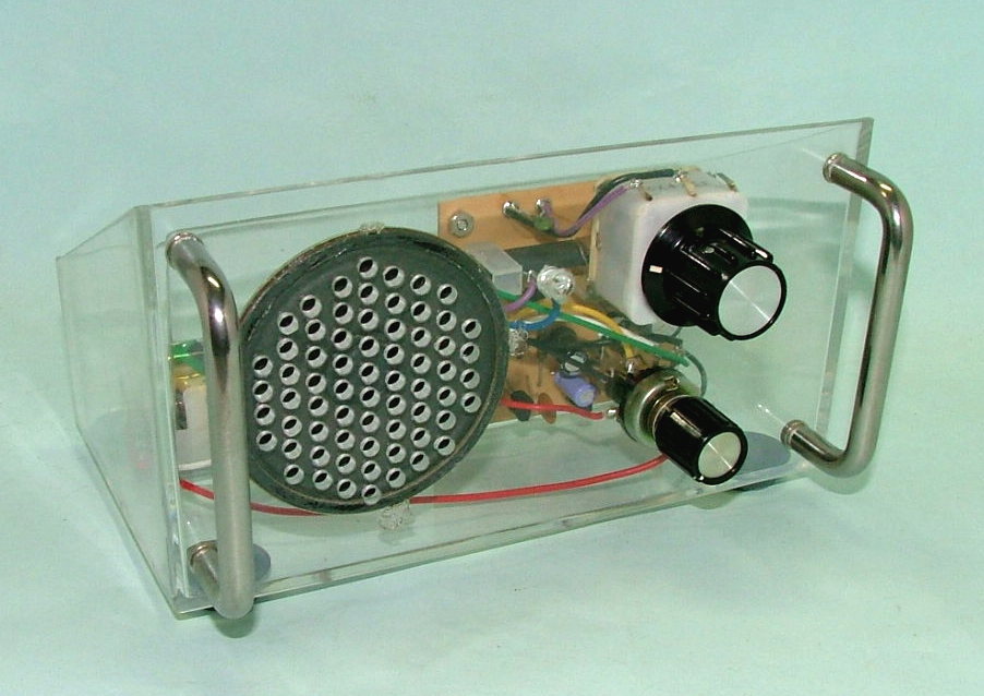
●Regenerative Radio in a clear plastic case
●2-TR Reflex Radio using Germanium Transistors
●2-TR Reflex Radio using Germanium Transistors
【1.1】Radio Receivers
Mr. Oshima, a friend of mine, discovered that a plain regenerative detector circuit is very sensitive when the detector tube's filament voltage is about half of its rated voltage even with very low plate voltage.
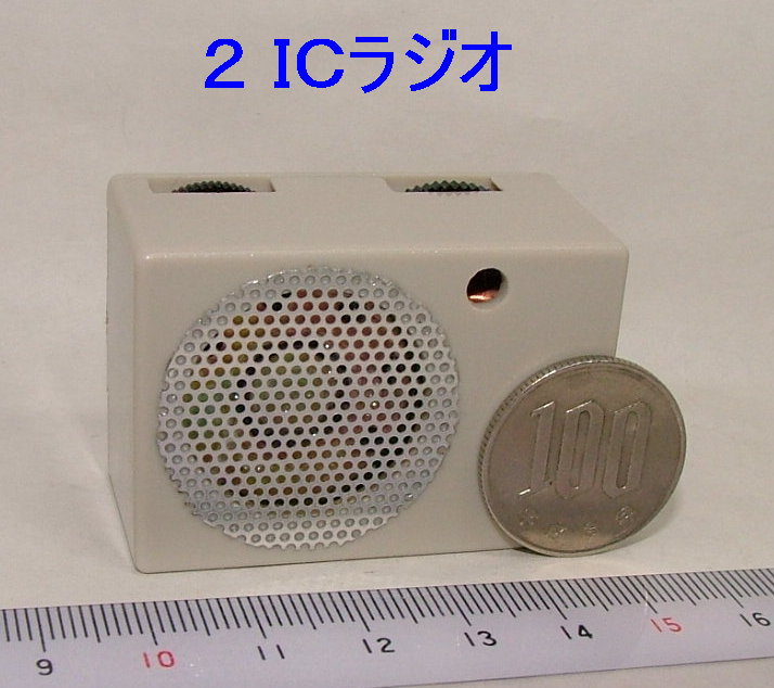
The size is 50×35×25mm but still with a built in speaker! The ICs used are the LMF501(equivalent of
the UTC7642 but with different pin asignment) and the TDA2822M with BTL connection for low voltage operation.

All the semiconductors, IFTs, audio transformers, both RF and AF, and the local oscillator coil are socketed for testing.

Receives signals between 535kHz to 150MHz by changing pug-in coils.

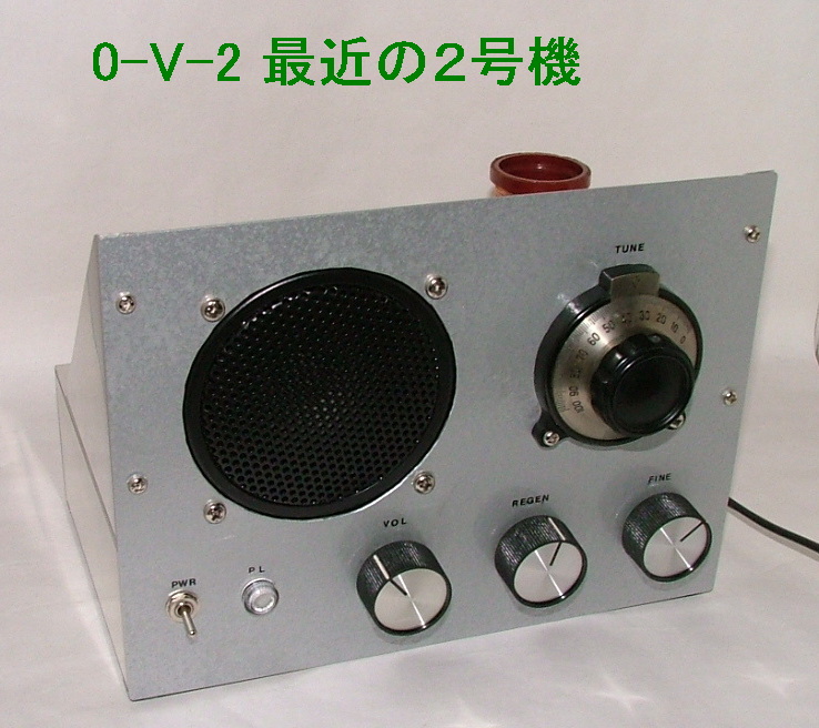
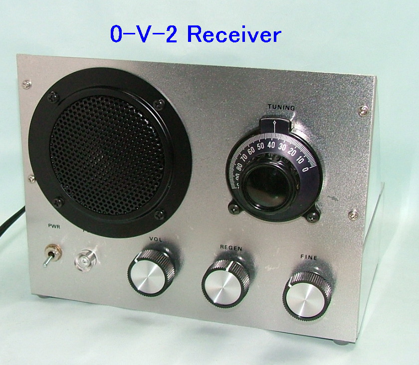
So called 1-V-2.

Normal 0-V-2s' sensitivity is varied by changing detector tube's G2 voltage. In this radio, the G2 voltage is fixed and the amount of feedback is changed.

The one is different from the one below (the (2nd Model) in that this one has a tuning indicator (small meter) though the needle does not move (deflect) a lot..
The parts layout and wiring is very similar to those of the kit. The kit was popular among the boys in the
1960's and early 1970's. This one is with a power transformer. To compare with the ones below that are
power transformer-less.
The tubes used are type 12AU6, 12AV6 and 50EH5. Different from the first model, the load of the detector tube
is a registor. Note how the heater voltage is obtained. It is half wave rectified AC100V = 70.7Vrms, which
is close to the the tubes' series connected heater voltage of 75V (12.6V+12.6V+50V). You cannot use type 60FX5 because its heater
current is different.
The tubes used are type 6AU6 and 16A8. The heater voltage is dropped by film capacitors. At first, I used
type 6EJ7 for 6AU6 hoping for better sensitivity. But higher gm did not result in higher sensitivity but in
the coil's lower tap position.

The tubes used are the 12AU6 and 50C5.
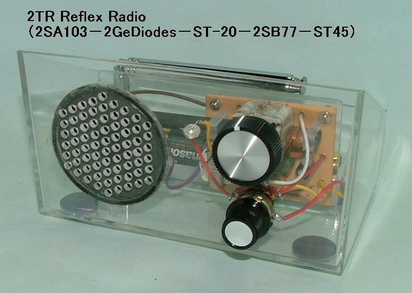
The circuit was used in many boy's radios. No RF transformer is used but two germanium diodes are used.
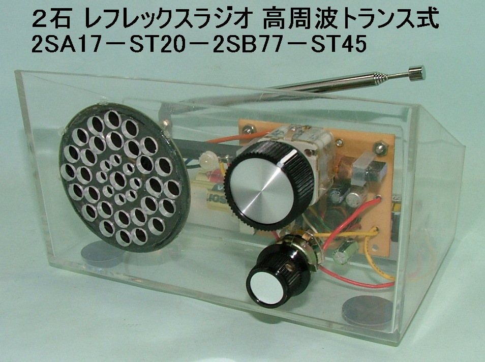
The circuit was used in many boy's radios. An RF transformer and one germanium diode is used.
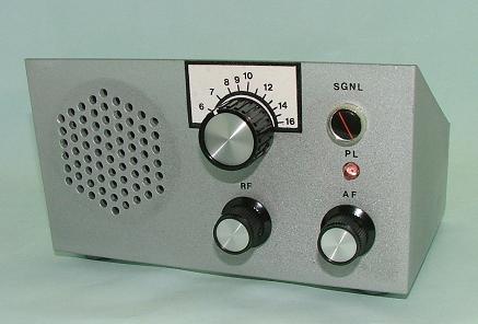
●IC+FET+6 Transistor Radio
A TRF radio using the UTC7642 (similar to the LMF-501). With a signal strength meter!
●IC+FET+3 Transistor Radio
TRF radio using the UTC7642 (similar to the LMF-501).
★2-Transistor Super Regenerative FM Radio
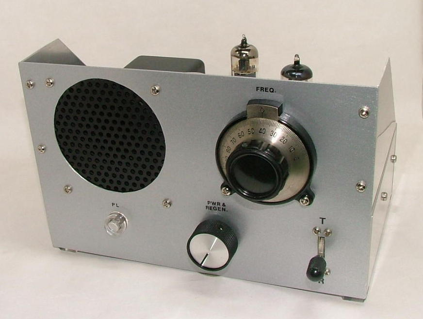
●Regenerative Radio
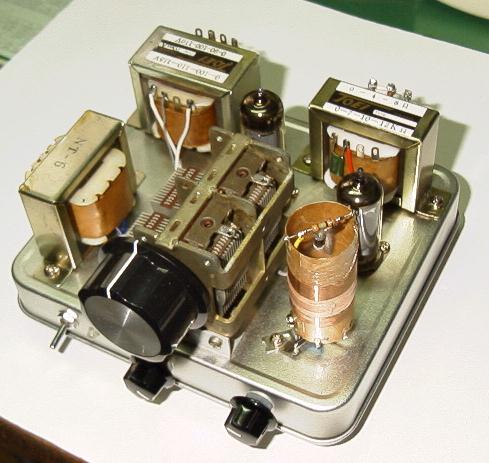
The tubes used are type 3AU6 and type 4M-P12(used for black and white TVs in Japan).
Inside the chassis
Schematic Diagram
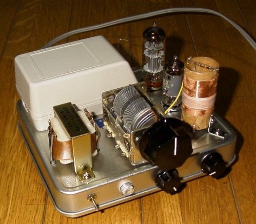
●Regenerative Radio
The tubes used are type 6AU6 and 6AB8.
Inside the chassis
Schematic diagram
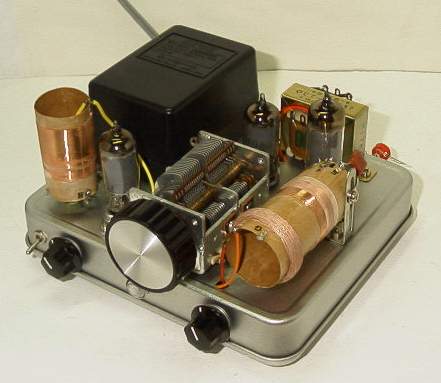
●Regenerative Radio with RF Amplifier Circuit
Inside the chassis
Schematic Diagram
●TRF Radio with Two RF Stages
The tubes used are type 6BD6, 6BD6 and 16A8.
Inside the chassis
Schematic diagram
★Multi-function Radio(External view)
★Multi-function Radio(Internal view)
★Multi-function Radio(Schematic diagram)
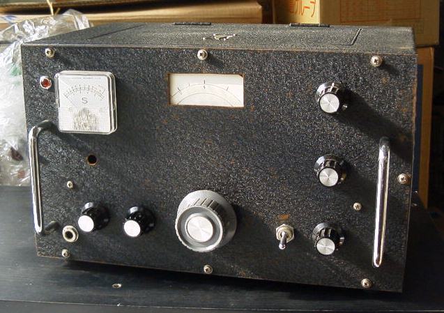
●Communications Receiver
I built this when I was 14 years old by myself after reading magazines. This receiver consists of an RF amplifier, a converter, a local oscillator, two IF amplifiers, a product detector, a BFO and an audio amplifier. I modified the local oscillator (separate tube for oscillatyor) and changed the audio amplifier to an IC (LM380N) later.
Inside the chassis (1)
Inside the chassis (2)
Schematic diagram (1)
Schematic diagram (2)
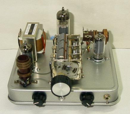
●Ultradyne Receiver
Receives signals between 535kHz to 150MHz by changing pug-in coils.
Inside the chassis
Rear view
【1.2】Various Projects/Gadgets
 ●2-Tube Super Regenrative Transceiver = Copy of a kit once sold by "Kagaku Kyouzai-sha"
The tubes used are type 12AU7 and 6AR5. The parts layout and wiring is very similar to those of the kit. The kit was popular among the boys in the
1960's and early 1070's.

●Digital frequency display for old BCL radios
This is a freqency counter with frequency offset (deduction) function. IF frequcncies to be
deducted are set by inserting diodes to the sockets. The maximum frequency is 31MHz.
Internal view
Connection to the ICF-5800
Modification of the 9R-59D
Output terminal added to the 9R-59D

●Loop antenna (with crystal radio)
★Schematic diagram for the loop antenna (with crystal radio)
★2-Tube Super Regenerative Transceiver 3 (External View)
★2-Tube Super Regenerative Transceiver 3 (Internal View)
★2-Tube Super Regenerative Transceiver 3 (Power Supply。
★2-tube Super Regenerative Transceiver (Outside)
★2-tube Super Regenerative Transceiver (Inside)
★Intercom
★7" LCD Monitor Module
★7" LCD Monitor (Picture)
★Pre-amplifier for the Communications Receiver (Outside)
★Pre-amplifier for the Communications Receiver (Inside)
★Ni-Cd/Ni-MH Battery Charger/Discharger
★Ni-Cd/Ni-MH Battery Charger/Discharger (Schematic Diagram)
★TV Audio Demultiplex Adapter-1
★TV Audio Demultiplex Adapter-2
★TV Audio Only Tuner (External View)
★TV Audio Only Tuner (Internal View)
★1st Power Supply for Tube Circuits (External View)
★1st Power Supply for Tube Circuits (Internal View)
★Depth Charge Game (External View)
★Depth Charge Game (Internal View)
★Voice Changer (for Karaoke)
★Timer (Front View)
★Timer (Internal View)
★High/Low Power Adjuster
★Power Failure Alarm
★AC Adapter with simple regulator circuit
★Universal Battery Holder
【1.3】Test & Measurement Equipment
★Tester for Small Semiconductors-External View
★Tester for Small Semiconductors-Internal View
★Tester for Small Semiconductors-Schematic Diagram
★1st Frequency Counter in 1978 (External View)
★1st Frequency Counter in 1978 (Internal View)
★2nd Frequency Counter
★4th Power Supply for Tube Circuits) (Front View)
★4th Power Supply for Tube Circuits (On the Chassis)
★4th Power Supply for Tube Circuits (Inside the Chassis)
★Schematic Diagram for the 4th Power Supply (1/2)
★Schematic Diagram for the 4th Power Supply (2/2)
★3rd Power Supply for Tube Circuits
★2nd Power Supply for Tube Circuits
★Oscilloscope (External View)
★Oscilloscope (Internal View)
★Electrolytic Capacitor (ESR) Tester in Poptronics July, 2001 Issue
★0-20V Power Supply
★Four Dip Meters Including My Home-Brew
★FET Type Dip Meter
★Schematic Diagram for the Dip Meter)
★Capacitance Meters (External)
★Capacitance Meters (Internal)
★Capacitance Meter (Schematic)
★Capacitance Bridge
【1.4】Audio Amplifiers
★45 SE Amplifier with Cathode Choke Drive Circuit
★45 SE Amplifier (Schematic Diagram)
★UX-50/WE300B SE Amplifier
★Universal Amplifier to Test Popular Triodes
★Universal Amplifier's Schematic Diagram 1/2
★Universal Amplifier's Schematic Diagram 2/2
★Amplifier to Test 211/VT-4C and Similar Tubes
★Schematic Diagram for the above Amplifier
★2A3 SE Amplifier (External View)
★6L6G SE Amplifier
★6550pp Amplifier
★V-FET Amplifier
【2】My Tube Collection
【2.1】American Vacuum Tubes (mostly)
★WE252A
★WE261A
★WE274A (Globe, Engraved ST and ST)
★Various WE300As
★WE300A Getter Types
★WE300B (Engraved)
★WE205D (Type numbers on the glass)
★WE VT-52 (Engraved)
★WE275A
★WE348A
★WE310A (So called "Small Punch" and "Large Punch")
★4 Pillar 112A-250
★4 Pillar 2A3, 6B4G, 80 and 280
★4 Pillar 10, VT-25 and VT-52
★4 Pillar 210
★4 Pillar 42
★10 and 210 in ST-19 size
★Mesh plate 45, 250 and 80
★171 and 112 (With no suffix "A")
★Silvertone 45A. The same size as 2A3.
★182B/482B
★183
★483
★10-pin miniature tubes
★6U7G
★6E5 with carbon coating
★KY-84
★Early 5U4GB with a different base (The guide pin is lost.)
★Single plate 2A3s by RCA Cunningham and National Union
★Nisshin (Japanese) 2A3
★Matsuda (Toshiba) 2A3
★OLDON (Japanese) 2A3
★Single plate 2A3 made by "Don" (Japanese). Scarce.
★UG-6P7G. Made in Japan in 1944.
【2.2】Japanese Original Tubes.
★UY-627B. "27B" with 6.3V heater.
★HT-5001. Space charge grid tube used for measuring minute currents and potentials.
★UX-111B (With a space charge grid for low voltage operation)
★TOYO 6E5D. The red "diamond" glows.
★3W-C5. Penta-grid converter tube.
★1A6B (Pentagrid Converter for Battery Operation)
★UZ-1C6B
★UF-109A (Triode for Battery Operation)
★UZ-109C
★UY-133A (Power Pentode for Battery Operation)
★UZ-133D (Pnetode + triode)
★UF-134
★UZ-135
★UX-167
★UZ-6001
★UY-6301
★UZ-6302
★M3156. Passes test as a 6CL6 on the TV-7.
★Sora. "Sora" means sky.
★RH2
★RH4, RH8 and DH2
★Kawanishi FM2A05A
★Toshiba 6G-R7
★UZ-30MC (Dual Triode for Battery Operation)
★Special 30. Thin.
★UY-510B (Transmitting Pentode)
★FZ-064A
★UY-807A
★UY-807B. The heater voltage is 12.0V
★T307
★TB-674-A (Same as 76)
★Toshiba No.3003 converter tube.
★KX-112B
★This tube's name is "One's own soul" but actually a 12A with a different pinout.
★UY-47B
★UX-47C (Triode)
★UY-76A
★Japan Radio Company UZ-42A
★6Z-DH3. 6Z-DH3A is common.
★Another sample of 6Z-DH3
★6A3B
★KX-80K. Type 80 with cathode.
★UX-80K. Type 80 with cathode.
★KY-84A. The heater voltage is 12.6V.
★KX-12FK
★3Y-P1. Substitute for the 47B.
★Another sample of 3Y-P1
★"Tou"'s ballast tube B-03A
★Ballast tube B-49
★Ballast tube B-61
★Type 1H3 eye tube. "!" turns green.
★ tube LS-2B (60 Volt voltage stabilizer tube)
★50DB1. 2 inch CRT.
★6MD4
★6WC5A
★The name is "Super Detection". Made by "Horizon"
★MB-655-A/CZ-504D
★US 6305
【2.3】Vacuum Tube Boxes
★Admiral
★Airline
★Amperex
★ARCTURUS
★CeCo
★CHIEF
★ConcertMaster
★CORONADO
★Crosley and IEC
★Cunningham (1)
★Cunningham (2)
★DeForest
★Delco
★DUMONT
★DUO_VAC
★Emerson
★GE
★GE Transmitting Tube
★Hytron VT-52
★ITT
★JRC(Johnsonburg Radio Company)
★Ken-Rad (1)
★Ken-Rad (2)
★Magnavox
★MARATHON
★Motorola
★Motorola (blue)
★Mullard
★National Union
★National Union (2) /A>
★PHILCO
★PhilipsECG
★RAD-TEL
★RAYTHEON (1)
★RAYTHEON (2)
★RAYTHEON (3)
★RCA
★RCA (2)
★RCA (3)
★RCA Victor (1)
★RCA Victor (2)
★Realistic
★ROGERS(Canada)
★RSE
★Shield
★Silvertone
★Silvertone (2)
★SPARTON
★SYLVANIA (1)
★SYLVANIA (2)
★SYLVANIA (3)
★Taylor
★Truetone
★Tung-Sol
★Tung-Sol (2)
★WE205D (1)
★WE205D (2)
★WE205D Canister
★WE300A
★WE274A (Engraved)
★WE274B
★Later WE Tubes
★WE CW-300B
★Westinghouse
★ZENITH
★6AR5 in military box
【3】Others
【3.1】Oscilloscopes and other test equipment
 ●500MHz Oscilloscope hp 54615B
 ●500MHz Oscilloscope hp 54610B
★SONY Tektronix 314 Oscilloscope
★SONY Tektronix 323 Oscilloscope
★SONY Tektronix 335 (and 336) Oscilloscope
★SONY Tektronix 336 Oscilloscope (50MHz with read out)
★Tektronix 464 Oscilloscope
★Tektronix 465 Oscilloscope
★Tektronix 465B Oscilloscope
★Tektronix 466 Oscilloscope
★Tektronix 475 Oscilloscope
★Tektronix 475A Oscilloscope

★Panasonic VP-5102B Oscilloscope
★2" and 3" Oscilloscopes
★hp 3580A Audio Spectrum Analyzer
★Two YHP 4260A LCR Bridges
★Meguro MQ-1601 Q meter
【3.2】Volt Ohm Meters
 ●SANWA's unusual shaped F-80TRD
No range switche? Listed in 1975 catalog.
 ●Tiny HIOKI TH-B36
Tiny! Listed in a catalog of a parts and kit venbdor in the mid 60's. An N battery is used.
★SANWA's old P-1B
★SANWA's old P-2
★SANWA's old P-2 (later version)
★SANWA's old P-3
★SANWA's old P-3H
★Sanwa's old K-20
★Sanwa JP-8D
★Sanwa YX-361TR
★SANWA's big old VOM (430ES)
★HIOKI P-70
★HIOKI TH-L33D
★Hioki OL-64D
★HIOKI 3021
★Panasonic RT-66 (Same as HIOKI F75J)
★Tachikawa 500TU (NOS)
★Hansen SU-2C. Design typical of old Hansen.
★Type H-10. Made by NAKAGAWA ELECTRIC INSTRUMENT WARKS???
★TOHO's made in 1948.
★TOHO 27-A.
★Erecor T-81
★Micronta (Radio Shack) 22-044
★Radio Shack 22-211A. Unique folding design.
★JEMCO US-105.
★ARC KRT-500
★My only British VOM.
★MS-1 made by Maekawa Scienilfic Apparatus. Similar to SANWA P-2 but a little bigger.
★Star TS-8K
★Yokogawaw's OEM for NEC. For US army (Type RTS-E-518)
★Yokogawa 2411. Believe it or not, Yokogawa.
★Yokogawa 2414. Believe it or not, Yokogawa.
★Yokogawa 2415. Believe it or not, Yokogawa.
★Kaise SK-300
★Kaise SK-310 (Repaired)
★OHKUBO OT-223 (Kit?)
★REGALのAT-2050型テスターはここです。
★島津のTC-11型テスターはここです。
★KAMODEN 22-150, also Micronta (Radio Shadk) 22-150. "KAMODEN" is a brand that did not last long.
【3.3】Other Equipment
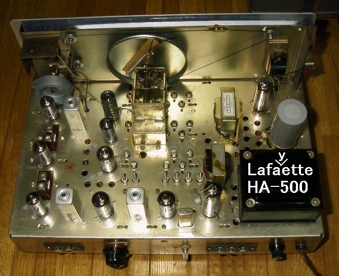
★Lafayette HA-500 Ham Band Receiver
★Lafayette HA-500 (inside)
★R388/URR Military Receiver
★Lafayette KT-200 Receive (Front)r
★Lafayette KT-200 Receiver (Spread dial)
★SONY CRF-180
★SONY ICF-5500M
★Toshiba TRYX 2000
★SONY Watchman FD-20
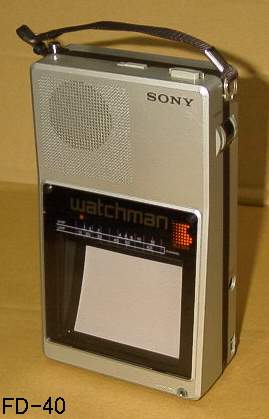
★SONY Watchman FD-40
【3.4】Radar Detectors in the 1980's in the U.S.A.
★ESCORT and PASSPORT
★BEL
★UNIDEN
★Whistler
★Cobra
★Fuzzbuster
★Fox
★Maxon and an old Radio Shack's
★Others
【3.5】Toy Transceivers
★Hinode HT-401
★takt
★TOMY
★Patrol_104 sold by Kimura Bussan Co., Ltd.
★Gakken "Radio Phone"
★Gakken CQ-4
★Gakken GX-3
★Gakken Marine
★Gakken CQ-6
★Gakken "New Radio Phone 6"
★Gakken's strange looking transceiver
★"MASCOT" 4-TR, with Morse Code
★FORTE TR-300
★TOWER. I bought the same model when I was 13.
★3-TR, Export model VF-30
★Muden. Stylish design.
★6-TR Muden
★4-TR Muden. Ugly.
★3-TR Muden. Ugly.
★3-TR "HEL-PHON"
★Only 2-TR Bandai
★Another 2-TR Bandai
★Koha Musen's 2-Tube Echo 3Q(front)
★Koha Musen's 2-Tube Echo 3Q(rear)
★Koha Musen's 2-Tube Echo 3Q(chassis)
★Koha Musen's 2-Tube Echo 3Q(top)
【4】How I Got Started
I was born in the suburbs of a small castle town in Gifu prefecture in Japan. (Please see http://www.iwamura.org/top/cg.htm if you have RealPlayer 10 software).
When I was 9 years old, I disassembled a 5-tube superhet radio at my mother's parents'. That was the first time I fooled around with electronic components.
A boy in the neighborhood who was 3 years older than I built a crystal radio. He taught me how to build one using the parts from the disassembled radio. But it did not work. So, I did not get hooked on radio at that time and kept building model cars using small motors and lamps.
When I was 11, I bought a crystal radio kit. I saw the ad in a magazine for models and radios. It worked! The bug bit me and my future was set! I found that my first crystal radio had not worked because the crystal earphone (receiver) was bad.
In that year, I disassembled a transistor radio for the first time. I found 2SC76, 2SD64.They were early Germanium NPN transistors, etc., which did not appear in projects in radio magazines. Too bad, I thought.
I started to buy radio magazines. (I should have asked my parents to buy me every issue.) I still keep those magazines. The bookstore in my hometown did not carry one of the popular radio magazines called "Rajio no Seisaku"(Constructing Radios). If I had read it, my knowledge on electronics would have improved quicker. It was not until I started to go to high school in a city next to my home town that I came across the
magazine.
My new year's resolution was "To build radios". Writing a resolution was part of the schoolwork and nobody else's was about his or her hobby and was traditional like "efforts" or "honesty". So, I felt I was out of place.
In 1969, I turned 12. Since this year, I was able to build some projects in radio magazines.
【5】Early Projects
【5.1】1 Transistor Code Oscillator #1
This was my first project from a magazine. I chose this project simply because this was the only one I can build with the components I had. It worked. I was very happy and I said to my parents "This one works!". I was disappointed because my parents
were not impressed. (I am sure my wife says I do the same to my kids.) I did not practice code and disassembled the oscillator soon.
【5.2】1 Transistor Amplifier/Code Oscillator
This amplifier is to amplify the output of a 1 transistor radio so that it can drive a speaker. I did not have a 1 transistor radio but I built it simply because I could find all the necessary parts in my junk box. I connected a crystal microphone to it but the sound from the amplifier is too small.
【5.3】1 Transistor Reflex Radio
I used the 2SA355. The case was a light blue Tupperware. With a telescopic antenna fully extended, it received a few local stations!
【5.4】1 Transistor AM Transmitter Kit
A 2SA156 and a carbon microphone were used in the kit. Use of a carbon microphone required only one transistor (as an oscillator). I had to wind a coil. It worked great. I bought this kit from a famous kit/parts shop called "Kagaku Kyozai Sha". The name means "Science Teaching Material Company". The company ran ads at the end of three magazines every month. I wished to buy such kits. Though two of the three magazines
("Mokei to Rajio" that means "Models and Radios" and "Shoho no Rajio" that means "Elementary Radio" do not exist any more, the kit company is still in business.
【5.5】2 Transistor AM Transmitter
Boys love transmitting devices. I used a coil that looked similar to the one used in the magazine without knowing that the inductance is the most important. As a matter of course, it did not work.
【6】When I was a Junior High School Student
【6.1】1 Tube (6AU6) Regenerative Radio
This was the first radio with a vacuum tube. It worked. 6AU6 was the detector. When I received the 6AU6 I mail ordered, I was a little disappointed because it was NEC brand. I thought Toshiba receiving tubes were the best at that time. At least Toshiba's were best looking.
【6.2】1 Tube (6GW8) Regenerative Radio
The triode part of the 6GW8 is the detector and the pentode part is audio power amplifier. When I used a 250PF capacitor in parallel with the grid leak, it did not work (loud noise like hum) but when I changed it to 100PF, it worked. Perhaps it was not the capacitance but a bad solder joint.
Why 6GW8 (not 6BM8)? Simply because I saw someone wrote in a magazine that the 6GW8 was newer and better that the more famous 6BM8. So, I kept using the 6GW8 for the 6BM8 or 6AV6+6AR5 until I picked up some 6BM8s from Hitachi TVs. In Japan, standard tubes for superhet radios were 6BE6, 6BA6 or 6BD6, 6AV6, 6AR5+6X4 or 5MK9.
【6.3】2 Tube AM Transmitter
This was a 6AV6 oscillator with the 6GW8 as the modulator. It worked fine. When I turned the volume up, I saw sparks in the 6AV6. While I was testing this transmitter, I got a call from my friend who lives about 1,000 feet away at the other side of a hill asking "Were you transmitting something?". The antenna I used was an about 200 feet long wire.
【6.4】1 Tube Audio Amplifier
An audio amplifier using the 6GW8 like the audio part of a typical 5-tube superhet radio plus a potentiometer for tone control. This was printed in a magazine's "Readers' Lab" page. Although the comments on my amplifier was not favorable, I appreciated the reward ($16 worth of money).
【6.5】0-V-1 Regenerative Shortwave Receiver
"0-V-1" means no RF amplifier, a detector and one audio amplifier stage. This may be Japanese original way of describing receiver configurations. Probably, I used a 6AU6 and a 6AV6. I built the circuit on a chassis I made with two pieces of wood and veneer board. It picked up Radio Australia. At that time, I did not imagine I would visit Australia on business 30 years later.
【6.6】0-V-2 Regenerative Shortwave Receiver
Probably I used a 6AU6 and a 6GW8. I built this one on an aluminum chassis. I did not want to wind a coil for the broadcast band (over 100 turns) and used a standard coil
for a regenerative receiver. I was happy to see it worked.
【6.7】3 Transistor AM Transmitter #1
This one had the same circuit as a kit from "Kagaku Kyozai Sha"(The famous kit/parts shop). Two transistors were used for audio amplification to modulate an oscillator. Among the AM transmitters with no RF amplifier circuit I tried, this one had
the longest range.
【6.8】3 Transistor AM Transmitter #2
I found this circuit in a magazine. Interestingly, it employed base modulation circuit and RF amplifier circuit. (I saw only four AM transmitters with RF amplifier in the radio magazines I ever read.) Somehow, it did not work.
【6.9】2 Tube Transceiver
The circuit is from a kit of "Kagaku Kyozai Sha's" kit. When I saw an old TV my friend got from his relative's, I saw the 7AU7. It instantly reminded me of the 2 tube transceiver kit from "Kagaku Kyozai Sha" that used a 12AU7 and a 6AR5.
A half of the 12AU7 is a super regenerative detector and another half is an audio amplifier. The 6AR5 is the audio power amplifier. The circuit is similar to the transceiver from another kit shop's model "2RQ". It was an AC version of the
famous transceiver using 3A5.
It worked fine. My friend also built one and we regularly talked over the transceiver. His house was located about 1,000 feet away beyond a hill.
【6.10】2 Transistor Radio
One transistor is used for RF amplification and another for audio. I saw this circuit among a series of simple radio projects by Mr. Hiroshi Izumi. It worked on only one battery and draw little current. So, I slept listening to this radio.
【6.11】Multi Function Radio
This radio has several functions. A superhet broadcast band radio, a broadcast band transmitter, a shortwave band transmitter, an AM tuner and a simple audio amplifier. Tubes are not installed. The tubes were; a 6BE6 for the converter, a 6BA6 for the IF, a 6GW8 for the audio and a 6AV6 for oscillator. I used four SD-1 silicon diodes I found in a discarded microwave oven. I found many of them in the microwave oven and used them for many projects.
【6.12】Shortwave Communications Receiver
After comparing various shortwave receiver articles I built this one when I was 14 years old. This was my biggest project. Many components are from old radios and TVs. I could not afford an expensive coil pack (switched coils for many bands) . So, this one receives 3.5 to 10MHz only. I could not afford a mechanical filter either.
I wanted to use a bigger and better looking cabinet but it was too expensive. This one is made of steel and it was not easy to drill holes.
The original configuration was as follows. 6BA6 for the RF amplifier, 6BE6 for the mixer/local oscillator, two 6BA6s for the IF, 6BE6 for the product detector, 6AV6 for the BFO, 6GW8 for the audio.
I did not have a power transformer large enough to power so many tubes but thought a regular one for 250V+250V @60mA for both waves rectification could be used as 250V 60mA plus 250V 60mA! Naturally, the voltage dropped considerably. I did not know that I should change the self bias resistor of the power output tube.
It worked after some minor corrections and I was very happy. In the 1971, only a few stations were talking in AM mode at 80m. I remember somebody was talking about his transmitter using a sweep tube from an old TV.
When I was a college student, I modified this receiver. I used a separate local oscillator, changed the 6BE6 product detector to include the BFO function, changed the audio amplifier to LM380. As a result, the local oscillator stability was improved and became stable about 45 minutes after turning the power on.
【6.13】Pre-Amplifier for the Communications Receiver
After listening to the 80m and 40m bands for a while, I noticed most stations' signal reports were "59" though my receiver's S meter indicated only 3 to 4 at most. I thought this was a problem and built a pre-amp using 6CB6. With the gain set to
maximum, my S meter reading was then close to 9 and I was happy. Do you laugh at me?
【6.14】6 Transistor Superhet Radio
You cannot finish the transistor course until you build a 6-transistor superhet radio. So I built one and took it to a school picnic. Nobody was impressed by it perhaps because the cabinet was a Tupperware.
【6.15】Grid Dip Meter #1
A grid dip meter is a must for RF projects. Because I could not get a power transformer with a 120V winding inexpensively, I used a heater transformer only and rectified the wall outlet 100V. I could not afford 6AK5, the standard tube for a dip
meter, and used the 5MHH3 from an old TV. 25 years later, the 6AK5 is chap and I bought several though I do not think I would use them. As for the coils, I had a good idea. I used a small male connector for the plug and put an 8mm coil form in it and
glued, which made a slim and good looking coil. I was happy with the result.
【6.16】TV Modified to an Oscilloscope
An article in a ham magazine showed how to modify an old black and white TV to an oscilloscope. Because I had experience with many such TVs (disassembled many such TVs to get parts) , I was able to understand and follow the instructions. I connected a microphone to the modified TV and talked to it. The waveform appeared on the CRT. I talked to the microphone loud saying "Uhhhh" and "Eeee", etc. Then my mother came to my room to see what was going on.
【7】Senior High School Days
There was a ham club station and I joined it. I took the test and got a no code ticket. Unexpectedly, my parents bought me a 6m transceiver (Panasonic RJX-601) and I got the call sign JR2PDC, which is still good now. But the last time I had a QSO was more than 20 years ago.
【7.1】Crystal Converter for 50MHz Band
During the summer holidays, I built a 6m crystal converter for my receiver (See above 6.12). It worked but the two stage RF amplifier generated lots of noise and, as a result, I felt like I was using a super regenerative receiver (too much noise).
Later, I had a chance to try a Kenwood JR-310, which also had lots of noise. I disassembled this converter somehow.
【7.2】3 Tube Transceiver with an RF Amplifier Stage
In a magazine, I saw a transceiver circuit similar to the one in above 6.9 but with an RF amplifier circuit. It looked promising and I built my version with the same circuit. The problem was that the transmit frequency was far apart from the receiving frequency though the coupling capacitor between the RF amplifier and the super regenerative detector was only 10PF. I removed the RF circuit and modified it for the 6m band. There used to be an antenna trimmer in the hole on the left of the dial. Transmit/receive switching is done by a relay. In January, 2004, I tested this unit and it worked!
【7.3】My First Regulated Power Supply
I built the variable voltage regulated power supply using a 2SB254 from a car radio, a 2SB77 and a 2SC371. The circuit was in the "Transistor Handbook" written by JA1AYO. The circuit does not look like short proof but it sure was. Later, I built my
second version with a 2SD147 and two 2SC536s. It did not use a zenner diode but used the base to emitter voltage (0.65V) as the reference which made the low-end voltage down to 1V or so. I disassembled it in 2000. I should have taken a picture
before that.
【7.4】Superhet Receiver for the CB Band
As usual, most parts were from old TVs and radios. A 6CB6 for the RF amplifier, a 6U8 for the mixer/local oscillator, a 6BA6 for the IF amplifier and a 6BM8 for the audio amplifier. It worked well but somehow I disassembled it soon.
【7.5】Code Oscillator #2
This is the first time I made a printed wiring board. I do not remember why a code oscillator again. (As a matter of fact, I do not like code.) Since then, I use the same method to make PWBs.
The above record confirms that, during my high school days, I could not spend a lot of time for the projects.
【8】Projects during My College Days
I joined the ham club station JA1YFL. There were many senior students who did very good at contents. But not from my year (joined in 1976) and after. Unfortunately, former members who joined in 1977 and after do not attend club reunions.
Although Akihabara (the biggest electronics district in Tokyo) was too far to visit often, I found various discarded electronics equipment for parts at scrap collection shop. I bought a brand new oscilloscope for the first time. It was a simple 75mm Kenwood 5MHz scope. It had a monitor circuit and a two-tone generator in it. I did not use those functions. So, I should have bought a used one with better performance. I
did not use it in the past 20 years and I sold it in 2000. At a scrap collection place, I found a CR oscillator. This way, I enjoyed my hobby.
【8.1】Stereo Tuner Amplifier
I disassembled a junk car stereo and using the modules salvaged from the car stereo, I built a tuner amplifier. I used the IF module and the amplifier module. I built a tone control circuit, a power circuit and added a FM front-end module. I built the cabinet using a large 1mm thick aluminum plate folded using tools in the college. I modeled a little after an old Yaesu receiver "FL-50B". I used it to listen to FM broadcasting and
to play cassette tapes. The first record I bought had lots of noise probably because of dust and so I hate records. So, I was very happy when CDs became available.
【8.2】Vacuum Tube Oscilloscope
At a scrap collection shop, I found an empty case which used to be a small simple old oscilloscope. I used the case to build a 50mm simple oscilloscope. I went to Akihabara and bought a CRT. The type number was "50TB1" which cost about $33. The vertical frequency range was up to several hundred kHz. The linearity of the sweep (time) signal was terrible. It looks like an antique oscilloscope. I still have it but without the 50TB1. I received some inquiries about the CRT (50TB1) bu it is not available in Japan now either.
【8.3】CB Band Crystal Converter
This was a crystal converter that converts the CB band to BC (broadcast) band. With this and a car radio, you can listen to CB. At first, I did not use a crystal for the local oscillator. The problem was that, when I adjusted the antenna circuit, the local oscillator frequency changed! So, I used a crystal oscillator. The local oscillator was 26MHz.
【8.4】TV Game
A TV game adapter to connect to a TV. with this, you can play tennis like games. This project was in a magazine. This set was based on the AY3-8500-1 LSI which cost about $33 worth of money. I played with it too much and was bored with TV games. So, I was
not interested in other TV games such as "Invader" and did not play with them though they were much more sophisticated.
【8.5】0-20V Regulated Power Supply
I bought this kit from Akizuki Densi Tsusho (a very famous parts/kit shop). This kit featured the low-end voltage of 0V! This kit did not include the cabinet, the meters or transformers. I used large meters from junk automotive test equipment.
【8.6】First Frequency Counter
At a scrap collection shop, I found some calculators that were bigger than today's notebook PCs. I disassembled them and found TTL ICs and fluorescent display tubes that looked like sub-miniature tubes. After reading articles in ham magazines and
learning basic logic circuit, I designed and built this frequency counter. I used a large 500KHz crystal. The frequency was a little too high. So, I opened the crystal case and touched the electrode with a marker (pen). The ink lowered the frequency. The first counter IC is the SN74196 and the maximum countable frequency was a little over 50MHz.
I did not use latch ICs. Instead, I disabled the display tubes during the count up process. The drawback is that the display repeats on and off in the low frequency (longer gate time) range. In the high frequency range, you do not notice it thanks to the after image. I built it in 1979 and still have it.
【8.7】Power Supply #1 for Tube Circuits
Based on a simple 200V regulated power supply circuit I found in a book, I built a variable regulated high voltage power supply. The power transformer (Type TPW-913A) was from an old Toshiba TV. The output voltages were 5V and 6.3V AC, and 150 to 400V DC. It has a simple output current limiting circuit. But when I shorted the output, all the semiconductors in the circuit (including a zenner diode) died.
Most black and white tube type TVs were power transformerless. However, Some Toshiba TVs had power transformers and therefore 6.3V tubes were used. Such TVs were very useful. There must be many OMs who built transmitters using the type TPW-913A power transformers.
【9】Projects After Getting a Job
I moved to Tokyo to start working in a company in April, 1980. Since then, I visited Akihabara often. Also, I was able to spend more money on the hobby.
【9.1】Capacitance Bridge (Recommended)
I built the first version while I was a junior high school student. The second one was based on the circuit of a January, '75 issue of CQ (a Japanese ham magazine). It required only one transistor for an audio oscillator and one
AA battery.
Originally, it had five ranges (full scale: 100PF, 1000PF, 0.01uF, 0.1uF and 1uF). I added a 50PF range, which made it possible to tell 1PF from 2PF. A smaller range such as 30 PF may be better. Because of stray capacity, you need separate scales for the range 100PF and below. The pictured one is my third one I built about 20 years ago. It was very useful until I bought a kit capacitance/inductance meter designed by a company "AADE" (almost all digital Electronics) a few years ago.
【9.2】2nd Frequency Counter
This is my second frequency counter I built in 1981. This one is based on a common LSI (ICM 7216B) with a cheap pre-scaler IC (HD 10551). The range is up to about 200MHz. In 2000, it went out of order. I found a register in a Schmitd trigger circuit changed considerably and the bias voltage changed. It was a cheap resister in a grab bag. Recently, inexpensive counters are available. But becauase I have two extra ICM7216Bs, I may build a third one that counts up to a GHz range. The best design may be based on a PIC but I have confirmed that I do not have talent for writing software.
【9.3】Audio Timer
I built this in 1980 using MM5316 (common at that time) LSIs. One of them triggers a solid state relay and the other resets it. They do not have a battery back up function. The indicator tubes on the right side (DG10R1) were salvaged from old calculators. I liked the color of the fluorescent indicators and I was happy when I found small transformers that have low voltage windings such as 4V, which is good for the filament.
【9.4】FET Dip Meter
I built the first one in 1981 though my Delica dip meter was still good. One reason was because I wanted to cover below 1.5MHz. I chose the circuit in one of the ham magazines. The frequency range is 400KHz to 220MHz. Compared with grid dip meters, The dip is shallow and the oscillation frequency varies more when you change the oscillation (signal) strength.
The coil at the right of the dip meter is for 200kHz to 1600kHz. I broke the ceramic form of an RF choke coil and remove the coil and glued it to a 8mm diameter form. The one in front of the dip meter is a plug with two alligator clips used when you use a crystal on the dip meter. In 2000, I disassembled the first one and built a second one which looks the same as the first one. I reused the same components excluding electrolytic capacitors and the case.
【9.5】TV Tuner for Multiplexed Audio
In 1980, I built a simple adapter type kit that decodes the second sound only. Then, I built this one based on an article in April issue of "Denpa Kagaku" (Radiowave Science). I added a VHF tuner and a UHF converter. It worked fine.
【9.6】Pulse Generator
This generator is incomplete. I built this in 1982 based on an article in February, 1975 issue of a Japanese magazine called "Toranjisuta Gijutu"(Transistor Technology). I confirmed that it works but I have not soldered capacitors for multiple ranges to the rotary switches. I will complete this one maybe after I retire.
【9.7】Charger/Discharger
I built this charger and discharger for Ni-Cd and Ni-MH batteries in 1992. Because of a several year blank, I had hard time drawing the circuit traces. I have not used CAD. In 2001, I designed a smaller PWB.
The battery holders are for discharging to avoid the "memory effect" and to adjust the discharging status. Pressing the green button starts discharging. The small round meter shows the voltage of each battery. When the battery voltage reaches to a certain value, a comparator stops discharging.
After discharging, you need to put the batteries in a separate battery holder and connect them to the constant current terminals at the top right corner. The current can be set by the switch (18mA, 50mA, 70mA or 120mA). More current ranges should
be added.
【9.8】Regulated Power Supplies
The one on the right is a tracking power supply for plus and minus 0 to 15V. I built it in1980. LM304 is used. The meters are cheap ones I bought in Hong Kong in 2000.
The one on the left provides constant current between 9mA and 500mA. The circuit is based on the LM317T. To achieve the wide current range, I used two variable resistors (100 ohms and 30 ohms) with a 0.47 ohm in series. I use this one for charging C and D size batteries mostly.
【9.9】Power Supply #2 for Tube Circuits
A successor to the first one (item 7.7). The circuit is a basic series pass regulator. The output voltage is between 200V and 470V. The stability is within -0.3% up to 100 mA output. This one provides 2.5V, 5V and 6.3V AC for the filament/heater. A over current protection circuit is used but I have not tested if it protects a short circuit or not because, if it does not, I may have to replace all the semiconductors.
If you plan to build one, I recommend a simpler and much better design that uses a Power MOS FET and the LM317T.
【9.10】"Ultradyne" Receiver
"Ultradyne Receiver" is a name of a receiver that a kit/parts vendor (Kagaku Kyozai Sha) used for one of their receivers. This receiver appeared in March ,1969 issue of "Mokei to Rajio"(Models and Radios) as a construction project. I built this receiver in 1998, finally. I am sure many boys longed for this receiver those days as I did. The pentode part of a 6GH8A works as a regenerative detector up to 25MHz and, between
25MHz and 150MHz, the triode part works as a super regenerative detector. Luxuriously, a 1:3 audio transformer is used. Probably this transformer picks up the leakage flux from the power transformer and I hear hum.
I bought the 1:3 transformer and some plug-in coil forms from Antique Electronic Supply. It seems that pins of the coil forms I bought are fixed to the base with help of an adhesive which easily melt with heat from a soldering iron.
I did not wind a coil for the BC band and used an antenna coil for a 5-tube superhet. I needed to add a cathode tap between the grid terminal and earth terminal.
【9.11】Improvement of a Spectrum Analyzer Adapter Kit
A few problems with the spectrum analyzer adapter kit from Akizuki Denshi Tsusho (the famous kit/parts) were pointed out in an article in "Mobile Ham" magazine. (Sadly, it went out of print in 2000.) So, I tried to improve the kit adapter. One ham
told me that a spectrum analyzer was required to make the kit work.
Improvements:
(1) I added a converter circuit to convert the output of the TV tuner to the frequency of the ceramic filter. (Originally 32MHz to 5.5MHz but 45MHz to 10.7MHz after the modification.)
(2) I designed a better sweep circuit using three transistors
(3) I replaced the FM radio IC used for the log amplifier with the famous MC3356P.
(4) I used a US band TV tuner, which resulted in wider band width (up to 450MHz). With the original one, the frequency range was up to 350MHz in two bands.
This kit does not come with PWBs. So I designed PWBs (excluding the power supply). The metallic box is a US band TV tuner. The small one on the right is the sweep circuit. Then, the power supply. The bottom center is the crystal converter. The bottom right is the ceramic filter and log amplifier.
As a result, I could get a clear spectrum on an oscilloscope CRT which looked like a real spectrum analyzer's. Thanks to the MC3356P, each one division on the screen can be exactly 10dB. I was very happy and kept watching the spectrum for a while.
(2) Around 250MHz, the sensitivity is low by almost 20dB. I think this is the TV tuner's problem.
(3) The frequency scale's (horizontal scale's) lenarity is very bad especially at above 350MHz. I think this is also a problem with the TV tuner though it is not a problem when it is used for a TV. As used in the article of Mobile Ham a 50MHz marker
oscillator will help you read the frequency. A wide band frequency synthesizer serves as a very good marker oscillator!
(4) The bandwidth of the IF filter is too wide. I wanted to use two SFE10.7MJs (the narrowest type of the SFE series) but was not able to get them and used similar but wider ones. (Thanks to Internet auction, I bought them much later but I have not tried them.) Buy the way, such ceramic filters are not good for a band scope for crowded ham bands.
Before I try a DBM based converter or the SFE10.7MJ, I bought a used spectrum analyzer and this adapter is still as pictured.
★The picture
【9.12】Power Failure Alarm
My parents raised chicken. The facility required electric power all the time and an engine generator needed to be started in case of a power failure. So, I built a simple AC power failure alarm. In case of power failure, a transistor switch activates an
oscillator circuit and it beeps loud. This is the (only?) project my parents appreciated most.
【9.13】Flash Light with Quake Sensor
I built this after thousans of people were killed by the big earthquake in Kobe area. I used mercury tilt switches as the eqrthquake (mothion) sensor. The flash light originally works on four size D batteries. I enclosed the sensor circuit for two of the batteries. Once it is activated by motion, the light keeps ON for about one minute. You can disable the motion sensor circuit by a switch.
I built about 8 of them for my parents, brothers/sisters and in-laws. This is the model I built most. Only children played with them for a while and I am afraid they have already forgotten what they were..
★The picture.
【9.14】4-Transistor Reflex Radio
I built this radio in 1999. The circuit consists of 2SA355 for an RF and AF amplifier, a 2SB75 and two 2SB77 for a push-pull output stage. I could not find a "varistor" (HV-15) and substituted it with a 2SB77. I adjusted the emitter resistor for minimum distortion. This project appeared in December. 1968 issue of "Shoho No Rajio" magazine.
This must be the most sensitive non-superhet radio project. The selectivity is s good as a superhet's and can separate all the seven stations in Tokyo area. A radio using LA1050 (IC) or a poorly designed regenerative receivers cannot do this. This radio is sensitive and its sound is as loud as a standard 6-transistor superhet. However, when I took it to my hometown in a mountain area, it could catch no station without an antenna during daytime.
In case you plan to build one, note that the battery polarity in the article is incorrect.
As an ex-"radio boy," I feel like building all the equipment that "Kagaku Kyozai-sha" sold those days (about 30 years ago).
|
Profile: My last name is Kato. | ||
|
Retired | ||
|
Telecommunication | ||
|
April 22 | ||
|
Male | ||
|
Iwamura-cho in Gifu prefecture (Japan) | ||
|
Kawasaki city (Japan) | ||
★My e-mail address here.